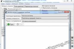
Antipyretic remedies for children are prescribed by a pediatrician. But there are situations of indispensable help for fevers, if the child needs to give faces negligently. Then the fathers take on themselves the resuscitation and stop the antipyretic preparations. What can be given to infants? How can you lower the temperature in older children? What are the most safe faces?
Passage of signals through resistive parameters. Frequency conversion
12.1 (O). Ideally, EPC creates a voltage (B) і= 1.5 cos 2π l0 7 t. A resistive element is connected to the zatiskachiv of the dzherel from the changeable conduction in the hour. G(t) \u003d 10 -3 + 2 10 -4 sin 2π l0 6 t. Find the strum amplitude IT, the frequency is 9.9 MHz.
12.2(O). The current receiver of the double range of assignments for the reception of signals in the frequency range of the f h min = 150 kHz up to f h max = 375 kHz. Intermediate receive frequency f pr = 465 kHz. Vznachte, at such boundaries, change the frequency of the local oscillator. f g of this primach.
12.3 (TO). At the superheterodyne receiver, the heterodyne creates harmonic vibrations from the frequency f r = 7.5 MHz. Intermediate receive frequency f pr = 465 kHz; With two possible frequencies, the signal that is received is given a higher frequency for the main receiving channel, and a smaller frequency for the mirror channel. To suppress the mirror channel at the input of the reversing frequency, a single corollary circuit is turned on, adjusting the frequency of the main channel. Find out the quality factor Q th circuit, if attenuation of the mirror channel in the warehouse - 25 dB 100% of the main channel of the receiver.
12.4(O). Differential steepness of a resistive parametric element, which enters before changing the frequency, changes according to the law S diff ( t) =S 0 +S 1 cos ω G t, de S 0 ,S 1 - constant numbers, ω d is the cutoff frequency of the local oscillator. Important, what is the intermediate frequency ω pr vidoma, know the frequencies of the signal ω with, for which blame the effect on the output of the rework.
12.5 (P). Passing characteristic of a field-effect transistor, tobto. stale stream stock i s (mA) і zi (B) at і hі ≥ -2 V, approximated by a quadratic parabola: i h = 7.5 ( u zi + 2) 2 . The local oscillator voltage is added to the input of the transistor і zi = Um g cos ω G t. Know the law of change in the hour of differential steepness S diff ( t) Specifications i h = f(і zi).
12.6 (UO). Chodo mind tasks 12.5 choose the amplitude of the voltage of the local oscillator Um g in such a rank, to ensure the coolness of the transformation S pr \u003d 6 mA / st.
12.7(O). At the frequency changeover frequency, the conductor diode, the CVC of which is described by the fallow (mA)

The voltage is applied to the diode to the local oscillator (V) u r = 1.2 cos ω G t. Calculate the coolness of the transformation S I’ll build this one.
12.8 (UO). At the diode switching frequency, which is the description in problem 12.7, a voltage (V) is applied to the diode u(t) =U 0 + 1.2 cos ω G t. vyznachte,
under any pressure U 0 < 0 крутизна преобразования составит величину 1.5 мА/В.
12.9 (UO). Frequency shifter circuit field effect transistor shown in fig. I.12.1. Kolivalny circuit is adjusted to the intermediate frequency ω pr = | ω h - ω p | Resonant contour support Rріз = 18 com. The sum of the voltage of the core signal (μV) is added to the input of the switcher u h ( t) = 50 cos ω c t and voltage to the local oscillator (V) u G ( t) = 0.8 cos ω G t. The characteristics of the transistor are described in chapter 12.5. Find the amplitude Um pr output signal at the intermediate frequency.
The passage of signals through the parametric reactive stake. Parametric subsidiaries
12.10 (R). Differential capacitance of a parametric diode (varactor) in the vicinity of the operating point U 0 to deposit according to the applied voltage і let's come rank: W diff ( u) =b 0 +b 1 (u-U 0), de b 0 (pF) ta b 1 (pF/V) - the leading numerical coefficients. Voltage added to the varactor u=U 0 +Um cos ω 0 t. Subtract the formula to describe the strum i(t) through a varactor.
12.11 (UO). The differential capacity of the varactor is described by viraz C diff ( u) =b 0 +b 1 (u-U 0) +b 2 (u-U 0) 2 . The voltage is applied to the varactor's clamping u=U 0 +Um cos ω 0 t. Calculate the amplitude I 3 third harmonics of the struma through the varactor, thus f 0 = 10 GHz, Um=1.5, b 2 = 0.16 pF/V2.
12.12(O). Varactor may parameters: b 0 = 4 pF, b 2 = 0.25 pF/V2. A high-frequency voltage with amplitude is added to the varactor Um = 0.4 V. Choose how much time the amplitude of the first harmonic of the struma I 1 same value Um dorivnyuvatime 3 Art.
12.13 (UO). The location of the parametric capacitor changes in hours according to the law W(t) =W 0 exp (- t/τ) σ ( t), de W 0 τ - constant values. Linearly increasing voltage is connected to the capacitor u(t) =atσ( t). Calculate the law change at the hour strumu i(t) at the capacitor.
12.14 (UO). Chodo minds tasks 12.13 know the moment of the hour t 1, which mitteva tension, shriveled by a capacitor to the signal, is maximum, as well as the moment of the hour t 2, which is the maximum tension that is shown by the condenser at the outside of the lance.
12.15 (P). Single-circuit parametric switch for connections from the side of the entrance to the EPC (generator) socket with an internal
support R r = 560 ohm. Pіdsilyuvach pratsyuє on resistive navantazhennya іz support R n = 400 Ohm. Know the value of conductivity to be applied G vn, which ensures the coefficient of strengthening of sweating BeforeR= 25 dB.
12.16 (O). For the parametric feeder described in problem 12.15, find the critical value of the conductivity to be applied G vn kr, for which the system is affected by self-excitation.
12.17 (UO). The voltage to the signal is added to the clamping of the ceramic parametric capacitor u(t) =Um cos( ω c t+π/3). The capacity of the capacitor changes in hours according to the law C(t) =C 0 "de φ n - cob phase cob pumping. Choose the smallest value after the module φ n, how to ensure the zero value of the conductivity to be entered.
12.18 (O). Number of minds tasks 12.17 for parameter values W 0 = 0.3 pF, β = 0.25 mA ω c = 2π 10 9 s -1 G ext max , as well as the smallest phase cut behind the module sra, secure this mode.
12.19 (R). Double-loop parametric substation of appointments for work at frequencies f h = 2 GHz. Idle frequency f cold = 0.5 GHz. Vikoristany in the substation varactor changes its capacity (pF) from the pumping frequency ω n zgіdno іz law W(t) = 2(1 + 0.15 cos ω n t). Dzherelo signal that adventitiousness may have the same active conductivity G r = G n = 2 10 -3 Div. Calculate the value of the resonant support of the idle circuit R rez.hol, with yakomu in pіdsilyuvachi vikaє self-excitation.
Linear-parametric lancets-radio-technical lancets, one or more of the parameters that change in hours according to a given law, are called parametric ( linear lancers with changing parameters). It is expected that the change of any parameter will be carried out by the electronic method for an additional signal of care. In a linear-parametric lance, the parameters of the elements lie equal to the signal, or they can change independently at the hour. Really parametric element is taken from non-linear element at the entrance of which, a sum of two independent signals is given. One of them carried information and may have a small amplitude, so in the area of yogo changes in the parameters of the lancet, it is practically constant. Another is a high-amplitude signal that changes the position of the operating point of a non-linear element, also another parameter.
In radio engineering, parametric supports R(t), parametric inductances L(t) and parametric capacitances C(t) are widely used.
For a parametric support R(t) with a variable parameter є differential twist
The butt of a parametric support can be a channel of an MIS transistor, on the gate of which a variable (heterodyne) voltage is applied u P (t). In this case, the steepness of the flow-shutter characteristics changes in the hour and is connected with a certain spring load S(t) = S. How to connect the voltage of the modulated signal to the MIS transistor u(t), then yogo strum be appointed viraz
The most widely parametric support for setting the signal frequency conversion. Heterodyne - the process of non-linear or parametric mixing of two signals of different frequencies for the removal of the third frequency, the result is a shift in the spectrum of the output signal.

Mal. 24. Structural diagram of frequency shifter
The frequency shifter (Fig. 24) is composed of a shifter (SM) - a parametric element (for example, an MIS transistor, a varicap, etc.), a local oscillator (G) - an additional harmonic generator with a frequency ωg, which serves for parametric control of the shifter , and the intermediate frequency filter (FPL) - smug filter
The principle of frequency shifting can be seen from the application of transferring the spectrum of a single-tone AM signal. It is acceptable that under the injection of a heterodyne voltage
![]()
the steepness of the characteristics of the MIS transistor varies approximately according to the law
![]()
de S 0 and S 1 - the average value and the first harmonic of the warehouse steepness of the characteristic. When it comes to the MOS transistor, what I change, zmishuvacha priymacha AM-signal
changing the warehouse of the external stream should be indicated by the viraz:
Let it go as the intermediate frequency of the parametric shifter, the frequency is selected
When analyzing the passage of a stationary SP through a linear electric lancet (Fig. 1), it is important that the lancet mode has been restored, tobto. after the signal was given to the entrance of the lansy, all the transitional processes, connected with the notifications, ended. This weekend joint venture will be stationary. The task, as it is seen, is reasonable in that, for the given correlation function of the input signal, either the spectral power of the intensity is determined B(t) either G(w) output signal.
On the back of the head, we can look at the rozv'yazannya tsgogo zavdannya in the frequency area. Input SP of tasks with its own spectral power of tension GX(
). Weekend spectral width tightness G y (w) is assigned to the formula) = GX( )K 2 ( ), (1)de K 2 (
) - The square of the module of the complex transfer function of the lance. The squaring of the module is based on the fact that the characteristic being measured is the effective function of the frequency and the energy characteristic of the output process.In order to define the connection between correlation functions, it is necessary to stop up to both parts of equality (1) of Four's reversal:
Bx(
) = F -1 [G x( )]; F -1 [K 2 ( )] = Bh( )Correlation function of the impulse response of the doslidzhuvanny lancer:
Bh(
)= h(t)h(t- )dt.In this way, the correlation function of the output SP is
) =B x( ) B h( ) = Bx( t)B h(t-t) dt.APPLICATION 1 passage of a stationary wide range signal through RC-lance (low-pass filter), represented by a diagram in fig. 2.
Broadband is understood in such a way that the energy width of the spectrum of the input SP is much larger for the amount of bandwidth of the lancet (Fig. 3). With such spіvvіdshnіnі mіzh form K 2 (
) that G x( ) you can not see the characteristics G x( ) in the area upper frequencies.Vrahovyuchi, what are the smooth frequencies, de K 2 (w) The light is adjusted to zero; lay down G x(
) = G 0 = constant. Such an allowance significantly simplifies the analysis. Todi Gy( ) = G 0 K 2 ( )For a given Lancug
) = 1/, then Gy( ) = G 0 /.Significantly energetic width of the output signal range. Exhaust joint pressure
P y = s y 2 = (2p) - 1 Gy(
)d = G 0 /(2RC), then e = (G0)-1 Gy( )d= p/(2RC).On fig. 4 shows the correlation function of the output SP and the spectral gap of the tension.
The spectral width of the tightness repeats the square of the module of the complex transmission function of the lance. Maximum value Gy(
) one G 0 . The maximum value of the correlation function of the output SP (iogo dispersion) is more G 0 /(2RC). It doesn't matter to designate the area, I will mark correlation function. There is more than the value of the spectral width of the tension for zero frequency, that is. G 0:.
It's easy to send your harn to the robot to the basics. Vikoristovy form, raztastovanu below
Students, graduate students, young adults, like a victorious base of knowledge in their trained robots, will be your best friend.
Placed on http://www.allbest.ru/
Control robot
Reconstruction of signals by linear lancets from constant parameters
1. Zagalni vіdomosti
5.1 Lancets of the integrating type (low-pass filters)
5.2 Differential type lances (high pass filters)
5.3 Frequency-selection lances
Literature
1. Zagalni vіdomosti
The electronic lantern is a collection of elements that ensure the passage of that transformation of the former and the changing streams in a wide frequency range. Vaughn includes dzherela electrical energy (dzherela zhivlennya), її spozhivachі and accumulative, as well as zadnuvalni droti. Elements of lancers can be divided into active and passive ones.
In the active elements, it is possible to transform the strums, or the tension and the one-hour increase in their tightness. Before them one can see, for example, transistors, operating devices and other.
In the passive elements, the transformation of the strums and the voltage to the increased tension are not accompanied, but the sound is guarded by the change.
Dzherela electrical energy are characterized by the magnitude of the direct electrical breaking force (e.f.f.) and the magnitude of the internal support. When analyzing electronic cells, they are understood by the concepts of ideal cores (generators) e.r.s. E d (Fig. 1a) and struma I d (Fig. 1b). stink (dzherela naprugi) that dzherela strumu, zvіdpovіdno generators e.r.s. (voltage generators) and struma generators.
Pid dzherelom e.r.s. rozumіyut so іdealіzovanе zherelo zhivlennya, е.д.з. Internal opir R g of the idealized dzherel life is zero
A strum generator is called such an idealized life, like a strum I g at the venture, so you can’t lie in the size of the її support R n. For schob strum I g dzherela strumu without lying down in the support of the advancement R n, internal opir yogo ta yogo e.r.s. theoretically guilty of incompetence.
Really dzherela naprugi that dzherela strumu mayut vnutrishnіy opіr R m terminal size (Fig. 2).
Passive elements of radio engineering lances can be seen electrical pylons(resistors), capacitors and inductors.
The resistor is energy saving. The main parameter of the resistor is the active opir R. Opir is expressed in ohms (Ohm), kilomah (kOhm) and megohm (MΩ).
Before accumulating energy, a capacitor (accumulating electrical energy) and an inductance coil (accumulating magnetic energy) are seen.
The main parameter of the capacitor is capacitance W. Mistkіst vymiryuєtsya at farads (F), microfarads (μF), nanofarads (nF), picofarads (pF).
The main parameter of the inductance coil is є її і inductance L. The value of inductance is measured in henry (Hn), milihenry (mH), microgenre (μH) or nanogenre (nH).
When analyzing circuits, it is necessary to note that these elements are ideal, which are justified by such differences between voltage drops u on the element and strum that flows through it i:
What are the parameters of the elements R, Lі W do not lie in the presence of ovnіshnіh vplivіv (voltage and struma) and can not increase the energy of the signal, which is in the lance, then they are called not only passive, but also line elements. Lanziugs, which avenge such elements, are called passive linear lancets, linear lancers with constant parameters, or stationary lancets.
Lantsyug, in a way an active opir, capacity and inductance of the introduction to the last її dilyanok, is called a lantsyug іz zoseredzhenimi parameters. As well as the parameters of the lancet of the expansion of the air, it is also important to respect the lancet of the separation of the parameters.
The parameters of the elements of the lances can change from time to time according to the law as a result of additional additions that are not connected with the pressure or the strum in the lances. Such elements (and folded lances from them) are called parametric:
A thermistor, which is based on the function of temperature, a powder-coated microphone with a ceramic coating under the vise support, is visible to the parametric elements.
Elements, the parameters of which lie down according to the size of the streams, how to pass through them, or the tension on the elements, and the interrelationships between the streams and the voltages are described, by non-linear equalities, called non-linear, and the lancers, who avenge such elements - non-linear.
Processes, which are inputted in lances with the help of parameters, are described by different differential equations, which connect between themselves input and output signals through the parameters of lances.
Linear differential alignment with constant coefficients a 0 ,a 1 ,a 2 …a n,b 0 ,b 1 ,..,b m characterizes the linear lancet with constant parameters
Linear differential alignments with changing coefficients describe linear lances with changing parameters.
Nareshti, processes, like in non-linear lances, are described by non-linear differential equations.
In linear parametric systems, I want one of the parameters to be changed for any given law. The result of converting a signal by such a system can be taken away by a way differential equalization zminnimi koefіtsіentsy, scho zv'yazuє mіzh themselves input and output signals.
2. Dominance of linear lances with constant parameters
As it was planned, the processes, like in linear lancers with constant seredent parameters, are described by linear differential equalities with constant coefficients. The method of folding such equals can be seen in the application of the simplest linear lancet, which is composed of successively joined elements R, Lі C(Fig. 3). Lansyug is excited by an ideal spring of a sufficient shape u(t). The task of analysis is based on the designated struma, which flows through the elements of the lancet.
Vіdpovidno to another law of Kirchhoff voltage u(t) increase the sum of the voltage drops on the elements R, Lі C
Ri+L = u(t).
Prodifferentiation tse equal, otrimaemo
The decision of the selected non-homogeneous linear differential alignment allows you to determine the required reaction of the lancer - i(t).
The classical method for analyzing the conversion of signals in linear lances is based on the significant stratification of such alignments, which are more expensive than the sum of the private solution of the outward heterogeneous alignment and the general solution of the uniform alignment.
The main solution of a homogeneous differential alignment is to lie in the same line (shards of the right of a part of the outlet level, which characterizes the inflow, are taken equal to zero) and are generally distinguished by the structure of the linear lance and cob minds. That is why the process, which is described as a warehouse solution, having taken away the name of a free process, and the warehouse itself - a free warehouse.
The private solution of a non-homogeneous differential equation is determined by the type of an alert function u(t). That’s why it’s called a vimushenoy (vimushenoy) warehouse, which shows on the її povnu staleness in the form of an open wake.
In this way, the process that goes into the lansy, you can see that it is composed of two processes, that are superimposed one on one - the muted one, which is how it was set in time, and the free one, which can only be under the hour of the transitional regime. Zavdyaks are free to store and reach the transitional process without interruption of approach to the muted (stationary) mode (become) of a linear lancer. In a stationary station, the law of change of all streams and the voltage of a linear lance, to accuracy up to constant values, is changed from the law of change of the load of the outer dzherel.
One of the most important powers of the linear lances, like the linearity of the differential equivalence, describes the behavior of the lancer, and the validity of the principle of independence of the overlay (superposition). The essence of this principle can be formulated by the offensive rank: when there are many strong forces on the linear lance, the behavior of the lancer can be determined by the path of the imposition of a solution, known for the skin forces of the okremo. In other words, in a linear lance, the sum of the reactions of the lancet lancet in different swells is greater than the reaction of the lancet in sumi diy. When you transfer, scho lansy is a vіlniy vіd pochatkovyh zapasіv energії.
From the theory of integration of linear differential equations from constant coefficients, one more fundamental power of linear lances is evident. Be-yakoy foldable dії in a linear lance with constant parameters do not blame new frequencies. This means that it is necessary to change the signals, which are accompanied by the appearance of new frequencies (that is, the frequencies included in the spectrum of the input signal), cannot, in principle, be designed for the help of a linear lance with constant parameters.
3. Analysis of the transformation of signals in linear lancets in the frequency domain
The classic method of analyzing processes in linear lancers often appears to be due to the need to carry out bulky transformations.
An alternative to the classical method is the operator (operational) method. The first day of the field is at the transition for the additional integral transformation over the input signal from the differential level to the additional level of algebra (operational). Then we will know the decision of which equivalence, for which, for the help of a pivotal transformation, the decision of the exit differential equivalence will be obtained.
As an integral transformation, most often vicorist transformation of Laplace, as for the function s(t) is given by the formula:
de p- Complex change: . Function s(t) is called the original, and the function S(p) - її images.
The reverse transition from the image to the original is created for the help of Laplace’s pivotal transformation
Vikonavshi Laplace's transformation of both parts equal (*), we take:
The Laplace image of the output and input signals is called the transfer characteristic (operator transfer coefficient) of the linear system:
Since the transmitting characteristic of the system is in the house, then the value of the output signal according to the given input signal is necessary:
· - Know the Laplace image of the input signal;
- Know the Laplace image of the output signal for the formula
- For images S wih ( p) to know the original (the output signal of the lancer).
As an integral transformation for the perfection of the differential equality, we can vikoristovuvatsya also the transformation of Fur'є, so let's call the transformation of Laplace, if it's changed p to avenge only a visible part. Significantly, in order to be able to zastosuvat Four's transformation to function, it can be absolutely integrated. Tse obezhennya znіmaєtsya at the time of the transformation of Laplace.
As seen, direct transformation of Fur'є signal s(t), specified in the clock area, є spectral width of the signal:
Vikonavshi transformation Fur'є both parts equal (*), we take:
Vіdnoshennya izobrazhenya Fur'є vhіdnogo and vhіdnogo signіlіv, tebto. variation of the spectral widths of the output and input signals is called the complex transmission coefficient of the linear lance:
As a linear system of inputs, the value of the output signal for a given input signal is vibrated by the offensive sequence:
· Vynachayut for the help of direct conversion Fur'є spectral width of the input signal;
Determine the spectral width of the output signal:
· For the help of the reversible transformation of Fur'є to know the exit signal, as a function of the hour
As for the input signal, it is necessary to convert Fur'є, the complex transfer coefficient can be subtracted from the transfer characteristics by replacing R on the j.
The analysis of the conversion of signals in linear lances with the help of a complex transmission coefficient is called the method of analysis in the frequency domain (spectral method).
In practice Before(j) is often known by the methods of the theory of lancers on the basis of important schemes without going into the fold of a differential equation. The methods are based on the fact that, with a harmonic influx, the complex transmission coefficient can be inverted when looking at the complex amplitudes of the output and input signals
linear lancet signal integrable
If the input and output signals are elastic, then K(j) є bezromіrnym, yakscho vіdpovіdno strum and tensile, then K(j) characterizes the frequency occurrence of the support of a linear lance, like a spring and a strum, then - the frequency occurrence of the conductivity.
Complex transfer coefficient K(j) of a linear lancet appears between itself in the spectrum of input and output signals. As if it were a complex function, there could be representations in three forms (algebraic, display and trigonometric):
de - Depth of module frequency
Phase deposition per frequency.
In a steep slope, the complex transmission coefficient can be displayed on a complex plane, adding along the axis of actual values - along the axis of apparent values. Otriman's curve is called the hodograph of the complex transfer coefficient.
In practice, it is more important than fallow Before() that k() look around. At what function Before() bear the name of the amplitude-frequency characteristic (AFC), and the function k() - phase-frequency characteristics (PFC) of the linear system. It is confirmed that there is a connection between the spectrum of input and output signals only in the complex area.
4. Analysis of the transformation of signals in linear lancets near the clock area
The principle of superposition can be changed for a specific reaction, allowing the cob reserves of energy of the linear lancet to be sufficient for the input. Rozrahunki at the same time seem to be the most simple, as if they gave an alert signal to the sight of a sum of standard warehouses of the same type, twisting forward the reaction of the lancer to the chosen standard warehouse. As a standard warehouse input signal, a single function (a single haircut) is often victorious 1( t - t 0) i delta pulse (single pulse) ( t - t 0).
The reaction of a linear lancer to a single haircut is called a transitional characteristic h(t).
The response of a linear lancet to a delta-impulse is called the impulse response g(t) of that lancet.
Since a single strobok is an integral in the form of a delta-impulse, then the functions h(t) that g(t) pov'yazanі mizh themselves such spіvvіdnoshennyami:
If any input signal of a linear lancet can be represented by a combination of delta pulses, multiplying the value of the signal at the time of the hour, depending on the position of these pulses on the clock axis. In this way, the connection between the output and the input signals of the linear lancet is given by the integral of the throat (Duhamel's integral):
The input signal can also be given by looking at the collection of single streaks, taken from the vagami, which gives a similar signal at the point of the cob of a single streak. Todi
The analysis of the transformation of signals with different impulse responses is called by the method of analysis in the clock region (method of integral overlay).
The choice of the time-clock-spectral method for the analysis of the conversion of signals in linear systems is dictated by the head rank, the accuracy of taking data from the data about the system by the simplicity of calculation.
The advantage of the spectral method is to operate with the spectra of signals, in the result it is possible to change the spectral width of the input signal in order to judge the change of its forms at the output of the system. With the best method of analysis in the hourly region in the wild, such an assessment of the growth is even more foldable
5. The simplest linear lancets and yogo characteristics
Since the analysis of linear lances can be carried out in the frequency or time domain, the result of signal conversion by such systems can be interpreted in two ways. Analysis of the clock area allows you to change the shape of the input signal. In the frequency domain, the result will look like a transformation over the frequency function, which will lead to a change in the spectral warehouse of the input signal, like in the end subbag it will show the shape of the output signal, in the timchasal region, like a transformation over the function of the hour.
The characteristics of the simplest linear kil are presented in Table 4.1.
5.1 Lances of the integrating type (low-pass filters)
Remaking the signal for the law
de m- Coefficient of proportionality, - value of the output signal at the moment t= 0, is called signal integration.
The operation of integrating unipolar and bipolar rectilinear pulses, which is an ideal integrator, is illustrated in Fig. 4.
The complex transfer coefficient of such an add-on is the amplitude-frequency characteristic, the phase-frequency characteristic, the transient characteristic h (t) \u003d t for t 0.
An ideal element for integrating the inlet stream iє ideal capacitor (Fig. 5), for which
Sound to put the task of integrating the output voltage. For whom it is enough to change the input voltage U input strumu generator i. A result close to this one can be taken, so that in series with the capacitor, add a resistor to complete the great support (Fig. 6), with a strum i = (U in - U wih)/ R mayzhe not lie in the voltage U vortex Tse will be fair for your mind U wih U input Todi viraz for external voltage (for zero cob minds U vortex (0) = 0)
can be replaced by nearby viraz
de - is expressed by the algebraic integral (that is, with the improvement of the sign) area under the signal on the interval (0, t) - the result of exact integration of the signal.
Steps of approaching a real output signal to the function to fall in U wih U in otherwise, scho mayzhe those same, in the form of a step of vykonannya of nervousness U in . Value wrapped proportional to value = RC, yaka took away the name of the fasting hour RC- Lanzug. Father, for the sake of victoriousness RC- lansyuga, as integrating is necessary, so that the hour of fasting will be great.
Complex transfer coefficient RC- lancets of integrating type
Having equalized the number of virases and the ideal integrator, we know that it is necessary to understand "1.
Tsya nerіvnіst is guilty of being satisfied with all the warehouse spectrum of the input signal, the zocrema and the least.
Transient characteristic RC- Lantsyugi integruyuchy type
In this way, an integrating-type RC-lancer can transform signals. However, it is often blamed for the need for a subdivision of electric coliving at different frequencies. Tse zavdannya vyrishuetsya for help electrical outbuildings called filters. From the spectrum of filings for the input of the filter of the electric ducts, we see (pass on the output) the ducting in the specified frequency range (called a smugogo transmission), and ignoring (relaxing) all other warehouses. By type of frequency response, filters are distinguished:
- lower frequencies, scho to pass colivannya with frequencies not higher than the actual cutoff frequency 0 (smug of transmission? = 0 0);
- upper frequencies, how to pass the noise with frequencies higher than 0 (smug of the pass? = 0);
- smug how to pass colivannya in the final frequency interval 1 2 (smuga pass? \u003d 1 2);
- rector zagorodzhuvalny, what to trim the noise at the given frequency smoothness (non-transmitting smug? = 1 2).
Type of frequency response RC- lances of an integrating type (Fig. 4.6. b) show what we can do to the right of the lancet, which is effectively skipped low frequencies. Tom RC-Lance of this type can be classified as a low frequency filter (LPF). For the boundary frequency of such a filter, take the frequency, de, tobto. the coefficient of signal transmission to the signal is reduced twice. Qiu frequency is often called by the frequency of sight h (cutoff frequency 0 ). Frequency at a glance
Dodatkovy phase zsuv, scho to be introduced RC-lance of an integrating type at frequency s, become - /4 .
To the langyugіv іntegryuchy type LR-lance with support at the exit (Fig. 6). Wait for the hour of such a lancer = L/R.
5.2 Lances of differential type (high-pass filters)
Differentiation is called a lance, for which the output signal is proportional to the input signal
de m- Coefficient of proportion. Complex transmission coefficient of an ideal differential device amplitude-frequency characteristic phase-frequency characteristic h(t) = (t).
An ideal element for converting the applied up to a new voltage into the strum I, change proportionally similar to an ideal capacitor (Fig. 4.7).
Sob to take the voltage, proportional to the input voltage, enough to turn the strum, which flows into the lance, i voltage, proportional to the struma. For whom to add in series with the capacitor, add a resistor R(Fig. 8, b) laying a small support, so that the law of changing the struma may not be changed ( i ? CDU in / dt).
However, for RC-lantsyugi, presented in fig. 4.8, a, output signal
that jealousy is near U in ( t) ? RCdU in / dt be fair less for your mind
From the improvement of the front virazu it is possible:
Vikonannya tsієї nerіvnosti accepting the change in fasting hour = RC, but when you change the value of the output signal U wih, it is also proportional.
More detailed analysis of the possibility of winning RC-lances as differentiation can be carried out in the frequency domain.
Complex transfer coefficient for RC-lances of a differentiating type are distinguished by virazu
AFC and PFC (Fig. 4.8, v) are given in vidpovidno to viraziv:
Based on the rest of the difference between the frequency response and phase response of an ideal differentiator, it is possible to create visnovok, so that for the differentiation of the input signal, the unevenness can be overcome. However, one can be satisfied with the entire frequency spectrum of the input signal.
Transient characteristic RC- lancets of differential type
The nature of the behavior of the frequency response RC- lances of a differential type show that such a lance is effectively passed high frequencies Therefore, it can be classified as a high pass filter (HPF). For the boundary frequency of such a filter, take the frequency, de. Її often called by the frequency of sight h (cutoff frequency 0 ). Frequency at a glance
For the great fasting hours f RC-Lances of a differential type, the voltage on the resistor repeats the change of the warehouse input signal, as if the warehouse were to be strangled. RC-lanciug in times is called dividing.
The same characteristics may RL-lance (Fig. 4.8, b), fast at the hour f =L/ R.
5.3 Frequency-selection lancers
The frequency-selection lances pass on the outside only the sound of frequencies, which lie prominently in a narrow fluid near the central frequency. Such lancers are often called linear smug filters. The simplest dark-colored filters є kolovalnі contours, studded with elements L, Cі R, moreover, in real circuits opir R(Opir vtrat) sound є active support of reactive elements.
Coiling circuits in the fallow land of the elements that are approved, according to the schedule to the weekend, are divided into the last and parallel.
The scheme of the sequential kolivalny circuit, if the output signal is the voltage, which is taken from the capacity, is shown in fig. a.
Complex transfer coefficient of such a circuit
How to increase the voltage and inductance in the sequential kolivalny circuit (Fig. 4.9, b), then
At the actual frequency of the input colivans in the last kolivalny circuit, there may be a resonance of the voltage, which manifests itself in the fact that the reactive supports of the capacitance and inductance become equal to the magnitude and prolongation to the sign. With this hot support circuit, it becomes purely active, and the strum circuit can have a maximum value. The frequency that pleases the mind
called the resonant frequency 0:
Size:
is a support module for any of the reactive elements of the kolivalny circuit at a resonant frequency and is called a characteristic (quite) support for the circuit.
The setting of the active support to the characteristic support is called the extinguished contour:
The return value is called the quality factor of the circuit:
at resonant frequency
Tse means the voltage on the skin reactive element circuit at resonance Q once shifted the voltage to the signal.
With the known quality factor of the real (included in any lance) sequential kolivalny circuit, it is necessary to protect the internal (external) opir R from the input signal socket (this opir is switched on sequentially with the active reference to the circuit) and the active opir R n navantazhennya (which should be connected in parallel to the outgoing reactive element). Looking back at the same quality factor
Sounds are evident, that the resonant power of the subsequent kolivalny circuit is most pronounced for low-resistance signal and at high-resistance voltages.
The overhead diagram of a parallel kolivalny circuit is shown in Fig. 10. In the guidance circuit, R is the active inductor reference, R1 is the active capacitor reference.
The input signal to such a circuit can only be a strum signal, but if the signal is a voltage generator, it will shunt the circuit.
The greatest interest is to become depressed, if opir R 1 capacitor W postіy strum and indistinctness. A diagram of such a circuit is shown in Fig. 4.10, b. І here is a complex transmission coefficient
The complex transmission coefficient of the parallel kolivalnoy circuit (that is the main support for the circuit) - we speak at the resonant frequency p, which satisfies the mind
de - Resonant frequency of the aftercooling circuit.
At the resonant frequency p
It is significant that at this frequency the streams that flow through the capacitor W that inductance coil L, Zsunuti in phase on, equal to the value of i in Q razіv reshuffle the strum I input dzherela signal.
Through the end of the inner support R Because of the signal, the quality factor of the parallel circuit changes:
Sounds sing, that the resonant power of the parallel kolivalny circuit is most clearly seen behind the signal bell with a great outward support ( R h "), so that the generatori struma.
For parallel kolyvalnyh circuits, which are vikoristovuyutsya in practice, with a high quality factor active opir vtra R significantly less than the inductive support L to that for the complex coefficient K(j ) let's mother:
Like viplyaє z tsikh virazіv, the resonant frequency of a high-quality parallel kolivalnoy circuit
The impulse response of such a circuit
yoga transition characteristic
For an ideal parallel kolivalny contour (a contour without vtrat, then R = 0)
The flow rate of the kolyvalny contours is introduced similarly to the flow rate smuga RC-lanzyugiv, tobto. as the frequency range, at the boundaries of which the module of the complex transmission coefficient shifts the level to the maximum (at resonance) value. With high Q-factors of the circuits and small deviations (displacement) of the frequencies, the frequency response of the series and parallel co-coil circuits is practically reduced to the resonant frequency. Tse allows you to take even closer, but in practice it is more convenient in practice to spread between a lot of transmission and parameters to the contour
Literature
Zaichik M.Yu. that in. Collection of initial and control tasks from the theory of electric kil. - M: Energovidav, 1981.
Borisov Yu.M. Electrical Engineering: Navch. guide for universities / Yu.M. Borisov, D.M. Lipatov, Yu.M. Zorin. - 3rd edition, revised. that dod. ; Grif MO. - Minsk: Vishch. school A, 2007. - 543 p.
Grigorash O.V. Electrical engineering and electronics: Navch. for universities / O.V. Grigorash, G.A. Sultanov, D.A. Standards - Vulture UMO. - Rostov n / D: Phoenix, 2008. - 462 p.
Lotoreychuk O.O. Theoretical foundations electrical engineering: navch. for stud. install media. prof. enlighten / E.A. Lotoreichuk. - Grif MO. - M.: Forum: Infra-M, 2008. - 316 p.
Fedorchenko A. A. Electrical engineering with the basics of electronics: Navch. for uchniv. prof. schools, lyceums and stud. colleges/A. A. Fedorchenko, Yu. G. Sindeev. - 2nd view. - M.: Dashkov i K °, 2010. - 415 p.
Kataenko Yu.K. Posibnik / Yu. K. Kataenko. - M.: Dashkov i K °; Rostov n / a: Academcenter, 2010. - 287 p.
Moskalenko V.V. Electric drive: Navch. helper for Wednesdays. prof. enlighten / V.V. Moskalenko. - M.: Maysternist, 2000. - 366 p.
Savilov G.V. Electrical engineering and electronics: a course of lectures / G.V. Savilov. - M.: Dashkov i K °, 2009. - 322 p.
Placed on Allbest.ru
Similar documents
Knowing the model of a two-wire transmission line. Characteristics of lanceugs with different parameters. A look at the methods of rozv'yazannya telegraph rivnyan. Features of the line transmission of electrical signals. Analysis of the equivalent scheme of the line plot.
presentation, donation 20.02.2014
Analysis of the dominance of the lancers, methods of their development of a hundred-linear lancers with permanent gerels. Proof of the power of linear lancers with additional laws of Kirchhoff. The principle of an equivalent generator. The method of equivalent conversion of electrical circuits.
presentation, added 10/16/2013
Razgaluzhene magnetic colo: understand that structure, elements and principles of their mutual modality. Scheme of substitution of a magnetic stake. The method of rozrahunka magnetic stresses. Rozrahunok lanzyugiv with linear and non-linear inductive elements, the designation of coefficients.
presentation, donation 28.10.2013
Designated operator function of the ARC filter. Analysis of the amplitude and phase spectra of the reaction. Pobudov's graph of the function to the hour of the reaction of the lancer. The designation of the transitional and pulse function of the filter. The reaction of the stake to a non-periodic rectilinear impulse.
course work, donations 08/30/2012
Ways to transform the sound. Zastosuvannya transforming Fur'є on digital processing sound. Powerfulness of the discrete transformation Fur'є. Median filtering of single-mode signals. Application of wavelet analysis between motions in a noisy signal.
course work, donations 05/18/2014
Formulating the laws of Kirchhoff. Rozrahunok lansyugiv with the last, parallel and zmіshanim half-shells of resistive elements. Transfer function of the lancet and yogo links with impulsive, transferable ta frequency characteristics lanceugs. Designated strums at the backs of the lanceug.
control of the robot 01/08/2013
Mittevy values. Vector flow diagram and topographic voltage diagram. Razrahunok showing wattmeters, voltages between set points. Analysis of transitional processes in linear electric lances with fixed parameters.
abstract, additions 30.08.2012
Scheme of substitution of an electric lance and positive directing of the stream of lines and phases. The balance of tension for the open phase. Active, reactive, the same tension of the 3-phase lancet. Spivvіdnoshennia between linear and phase values in a symmetrical system.
control of the robot 03.04.2009
Basic understanding and purpose of discrete transmission systems. Signal narrowing with AFM and quadrature AM. Spectral characteristics of signals from AFM. Modulator and demodulator of signals, stability to the overshoot of coherent signal reception from AFM.
thesis work, donations 07/09/2013
Understand that apply simple resistive lances. Methods of rozrahunka simple resistive kіl. Rozrahunok of resistive electric lances in a path of strums. Nodular stress method. Describing colivannya in resistive lances by linear algebraic lines.
Tsіkaviti and korisnimi for radio engineering dodatkіv authorities may linear systems, which are described by non-stationary system operators, which can lie in the hour. The law of transformation of the input signal can be seen here
![]()
why the problems of linearity of the system
for any fast
Lanciuges that are described by equivalence (12.1) are called parametric. The term refers to the fact that in the warehouse of such lances of footwear there are present elements, the parameters of which are to be deposited at any time. In radio engineering lancers, there are such parametric resistors, capacitors and inductances
Vіdmіnna rice linear parametric system - the presence of an additional dzherel kolivan, which controls the parameters of the elements.
An important role, which is played in radio engineering by parametric lances, is determined by the ability to transform the spectrum of input signals, as well as the possibility of creating low-noise parametric subsidiaries.
12.1. Passage of signals through resistive parametric lances
The parametric lance is called resistive, because it is the system operator of the number , which can be deposited at the hour and serve as a coefficient of proportionality between the input and output signals:
The simplest system of this kind is to serve as a parametric resistor with a support. The law that relates the value of the voltage to that struma in any two-terminal network is as follows:
![]()
The parametric resistive element can be described as a changeable conductivity
Implementation of parametric resistive elements.
Really parametrically keratinized resistors are created like this.
At the input of an inertia-free non-linear bipole with a current-voltage characteristic, a sum of two voltages is applied: the voltage that controls, and the voltage of the signal. The strum for a non-linear bipole can be written down by expanding the current-voltage characteristic in a Taylor series mitte meaning current voltage:
The amplitude of the signal is chosen to be small, which in formula (12.5) can be modified by other and larger steps of the magnitude.
Below, it will be important to place parametric resistive elements in the considered form.
Frequency conversion.
This is the name of the transformation of a modulated signal, which is connected with the transfer of the first spectrum from the vicinity of the carrier frequency to the vicinity of the current intermediate frequency without changing the modulation law.
The frequency shifter is composed of a shifter - a parametric inertial-free element and a local oscillator - an additional harmonic generator with a frequency of service for parametric control of the shifter. Under the influence of the voltage of the local oscillator, the differential steepness of the current-voltage characteristics of the zmishuvach periodically changes at the hour according to the law
As at the input of the frequency changer, the voltage is applied to the AM signal, it is possible to change (12.6) and (12.7) at the output stream, there are warehouses, see

As an intermediate, it is accepted to select the frequency of the strum at the intermediate frequency
є AM-columns from the same modulation law, like an input signal.
To see the warehouse spectrum with frequencies close to the intermediate frequency, the external lancet turns on the chimney circuit, adjusting to the frequency

Mal. 12.1. Structural diagram of a superheterodyne primach
The frequency conversion is widely changed in radio receivers - about superheterodynes. The block diagram of a superheterodyne primach is shown in fig. 12.1.
The signal received by the antenna, through the input filtering lances and the radio frequency substation (URCH), should reach the reversal. The output signal of the convertor is modulated with a carrier frequency, which is equal to the intermediate frequency of the receiver. The main strength of the reception of this frequency vibrancy, i.e., the ability to see the distortion signal from the transitions to lower frequencies, is protected by a high-frequency intermediate frequency (UPC).
The great advantage of the superheterodyne is the immutability of the intermediate frequency; in order to fix the primach, it is necessary to change the local oscillator only and in certain types of kolivalnі system, yakі є at the input lances and URC.
Significantly, the frequency shifter, however, reacts to signals from the frequencies of radio engineering, it seems that it is possible to receive both the main and the mirror channel. In order to eliminate the ambiguity of the reception, it is necessary to ensure such a vibrancy of resonant systems, switching on between the antenna and switching frequencies, in order to practically suppress the signals of the mirror channel.
The steepness of the transformation.
The efficiency of the frequency shifting operation is usually characterized by a special parameter - the twisting rate, as a coefficient of proportionality between the amplitude of the intermediate frequency stream and the amplitude of the non-modulated voltage signal, tobto.
![]()
Also, the steepness of the transformation is the old half of the amplitude of the first harmonic of the differential steepness of the parametric element.
Assume that the current-voltage characteristic of a non-linear element, which enters up to the frequency change, is quadratic: . At the signal to the element, the sum of the voltages of the displacement of the local oscillator is applied:
The differential coolness of the turnaround is changing at the hour of the law
Roll up to formula (123)
![]() (12.11)
(12.11)
In this way, with a constant equal to the core signal at the input, the amplitude of the output signal changes in proportion to the amplitude of the local oscillator voltage.
Example 12.1. A non-linear element (transistor) with a characteristic that can change the frequency of the chirps has a parameter Resonant support of the bellowing circuit of the collector lance. The amplitude of the modulated input signal is the amplitude of the local oscillator voltage. Know the value - the amplitude of the voltage of the intermediate frequency at the output of the converter.
For the formula (12.11) we can calculate the rotational speed of the collector. It is important to make the output of the transistor high, so that it is possible to suppress this shunting drive on the kolyvalny circuit, of course
Synchronous detection.
Assume that the frequency of the local oscillator shifts exactly to the frequency of the signal, so the differential steepness changes at the hour according to the law
Having applied to the input of such an AM-signal, we will take the signal for the stream of the signaled:
Viraz, what to stand here at the square arms, to take revenge on the post-storage, like to lie in the phase out of phase between the local oscillator signal and the incomprehensible input signal. Therefore, a low-frequency warehouse appears in the spectrum of the outer stream.
this stream is proportional to the changing amplitude of the AM signal.
A synchronous detector is called a reversal of frequencies, which works for the mind; to see the coris signal at the output of the low-pass filter, for example, a parallel lance RC.
In case of varying synchronous detectors, it is practically possible to increase the frequency of phase shifting between the incomprehensible input signal and local oscillator oscillations.
The most pleasant mode of operation, as well as the correct output signal during the day. Sensitivity of the synchronous detector to the phases allows to vikoristovuvat yogіryuvannya phase spіvvіdneniya between two coherent waves.
Shown below is a specific technique for a synchronous detector.
Example 12.2. A synchronous detector has a transistor, the characteristic of which is approximated by two straight lines. Approximation parameters: . Amplitude of the local oscillator voltage, constant voltage displacement in the daytime. Signify the change in the level of the constant voltage at the output of the synchronous detector, which is followed by a brown signal, like a resistance resistor.
With this type of current-voltage characteristic of a non-linear element, the differential steepness can take on more than two values:

Therefore, the schedule for changing the differential steepness in hours is the periodic sequence of rectilinear video pulses. Kut vіdsіkannya struma, which signifies the trivality of these impulses, is known by the formula (div. ch. 2)
Laying out the function in the Four's series, we calculate the amplitude of the first harmonic of the coolness:

The blue signal calls out clearly (12.13) to increase the struma through the transistor by the value . It is important to change the constant voltage at the output of the synchronous detector:
Signal spectrum at the output of a resistive parametric element.
The analysis of the robotic reversal of the frequency of the synchronous detector is changed, which in the parametric resistive element causes the spectral warehouses to be blamed, as it is daily at the input of the element.
Let's look at the parametric transformation of the mind (12.3) from the upper positions spectral analysis. Obviously, the parametric resistive element functions as a multiplier of the input signal and
Let's write down the following consistency between signals and Four's transformations:
On the basis of the theorem about the spectrum of the creation of signals (div. Ch. 2), the spectral width of the output signal is a
 (12.14)
Applied practice is of great interest to change, if it is necessary for the treatment to be periodic with a given set period and you can submit the order Fur'e
 (12.15)
de - Kutova frequency keruyuchy signal.
Apparently, a similar signal, which is not integrated, has a spectral width, more than zero at discrete points on the frequency axis:
 (12.16)
Substituting the formula (12.14) for the virase, we take the spectrum of the signal at the output of the parametric element:
 (12.17)
The spectrum of the gated signal.
The analysis of the general formula (12.17) should be carried out by hand in a hundred and fifty-fifty private, but in practice widely extended view. Let the keruyucha function stretch the skin period until the loneliness in the midst of the hour of trivality; At other times, the function is equal to zero.
In radio engineering, the operation of multiplying a signal by a function of this kind is called a strobe signal.
It is easy to perekonatisya, that the coefficients of the complex Four's series (12.15) of a fully analyzed strobe function are shown in this order:
 (12.18)
de - sparuvatist strobirukyatsey sequence.
Substitution of this result formula (12.17) to bring up the list about those that are the spectral width of the gated signal